DESIGN RULE HIERARCHY
Introduction
Given that you can create several design rules that potentially overlap each other, it is very important to understand how the design rule system works.
Proteus PCB Layout supports a hierarchy of rule types in increasing order of precedence. A rule in a higher priority level of the hierarchy will take priority over an overlapping rule that is in a lower priority level of the hierarchy. Where two or more rules still apply after the hierarchy has been resolved, the rule with the highest specified clearance in a given situation will "win". This largest wins behaviour is not confined to ties within a single level: it applies to every rule that survives the hierarchy.
The simplest way to understand this is that a more specific rule takes precedence over a more general rule; for example, a rule confined to a specific layer will take precedence on that layer over the default rule which governs the entire board.
The following is an explanation of the rule types, starting from the lowest priority level of the rule hierarchy and working up to the highest priority level of the hierarchy.
Design Rule Hierarchy
Board Rule
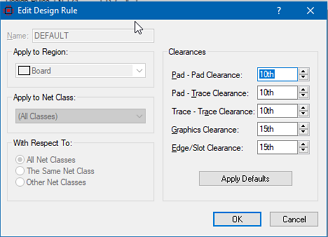
These are rules that apply to all layers on the board and to all electrical net classes. There is only one default rule (sometimes called the PCB rule) and that pre-supplied when you start a new project.
The default rule cannot be deleted for obvious reasons and cannot be changed to apply to specific layers or net classes.
This rule is at the lowest level of the design rule priority tree, meaning that any additional design rules will take precedence on the layer or net classes that they affect.
Layer Rule

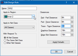
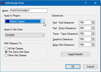
A Layer Rule is a rule with clearances that apply to all routes and pads but is confined to a single layer of the PCB. Use this to reduce the physical scope of the rule while still applying it to all objects.
Per Layer rules take precedence over the PCB rule but are lower in precedence to all other rule types.
Class Rule (All Layers)
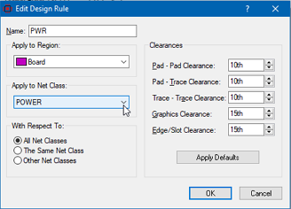
A Net Class Rule is a rule with clearances that apply to a given net class on all layers of the PCB. Use this to restrict the rule to specific signals (net class) wherever they might be on the PCB.
This rule will take precedence over both the PCB rule and any Per Layer Rules.
Class Layer Rule 
This is a rule where the clearances apply to a specific net class only on a specific layer. This rule restricts both the scope (to the layer) and the signals (to the net class).
This type of rule will take precedence over all the aforementioned rule types and in particular will take precedence over a Per Net Class (All Layers) rule.
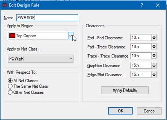
Class Class (All Layer)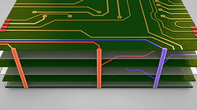
A Class Class rule is one where the clearances apply to a specific net class but with respect to either itself or to all other net class. In other words, a rule such that the clearances apply only between traces and pads on the same net class or if you set up a rule where the clearances apply only between traces and pads on one net class against traces and pads on any other net class.
In this case, the Inter net class rule applies to all layers.
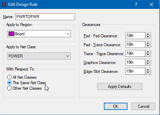
Class Class Layer 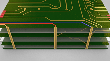
Exactly as above except that the inter net class rule applies to a specifically designated layer.
Room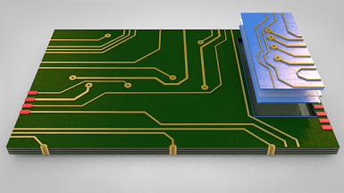
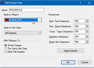
A room is a user drawn and named area of the PCB. It is the smallest physical scope you can specify for a rule, even though it can occupy several layers in the Z-direction. The important thing to remember about a room is that it overwrites all of the above rules.
So, a room rule wins over every rule below it in the list, whatever its electrical scope. This is worth reading carefully. A room rule does not simply out-rank the rules beneath it in the usual way: inside the room it culls them all, including a Class-Class Layer rule that is electrically far more specific than the room rule itself. Nothing that was inherited from the board, from a layer or from a net class survives inside the room boundary.
The one thing that limits this is net class coverage. A higher priority rule only displaces a lower priority one where it covers at least the same net classes. A room rule that names a single net class therefore leaves the inherited rules in place for every other net class in the room, which is what makes it possible to change the clearances for one signal group inside a room without disturbing anything else.
Class Room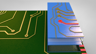
A class room rule provides an electrical filter inside the room, allowing you to specify different clearances for a specific net class that apply inside the scope of the room. Use this kind of rule for example to set up clearances for sensitive nets in the fanout region of a BGA.
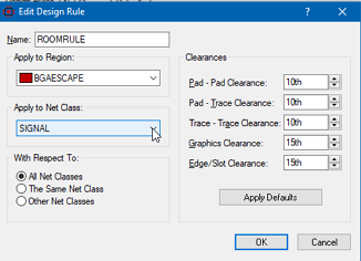
Class Class Room
A class class room rule is the highest priority rule available. It defines the clearances for a net class either with respect other objects on the same net class or with respect all other objects inside the scope of the room. It's exactly the same as the class class rule and the class class layer rule but this time the physical scope of the rule is the room.
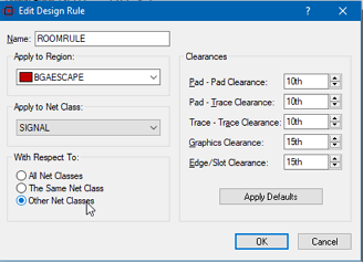
While this may sound complicated it is in fact quite intuitive in use. We recommend you read through the examples provided in the section below to make sure you understand how the system works.
Summary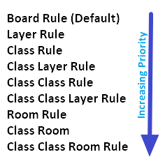
In terms of increasing priority design rules work as follows:
- Default: Whole board.
- Layer: E.g. A rule for Top Copper or for all inner layers.
- Class: E.g. A rule to apply to the POWER net class.
- Class-Layer: E.g. A rule that applies to the power net class on top copper.
- Class-Class: E.g A rule that applies to the POWER net class with respect to itself.
- Class-Class Layer: E.g. A rule that applies to the POWER net class with respect to itself on Top Copper.
- Room: E.g A rule that applies inside a placed room called BGAFANOUT.
- Class-Room: E.g. A rule that applies to class POWER inside a placed room BGAFANOUT.
- Class-Class-Room: E.g. A rule that applies to class POWER with respect to all other classes inside a placed room BGAFANOUT.
See Also: